This online version of the SCATT MX-W2 and Expert manual is published with permission from SCATT. I hope that this online version will make it easier to read and find solutions in mobile devices and searches. Download the latest version of their manuals here. Whenever you see text in italics it means that I've added that note. Check out my SCATT MX-W2 review all the SCATT articles.
This online version of the SCATT MX-W2 and Expert manual is published with permission from SCATT. I hope that this online version will make it easier to read and find solutions in mobile devices and searches. Download the latest version of their manuals here. Whenever you see text in italics it means that I’ve added that note. Check out my SCATT MX-W2 review all the SCATT articles.
Dear shooter,Thank you for choosing the SCATT Training System. To ensure optimal performance and safety, please read this User Guide entirely.
Table of Contents
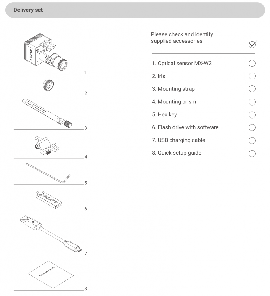
Delivery set
Optical sensor MX-W2
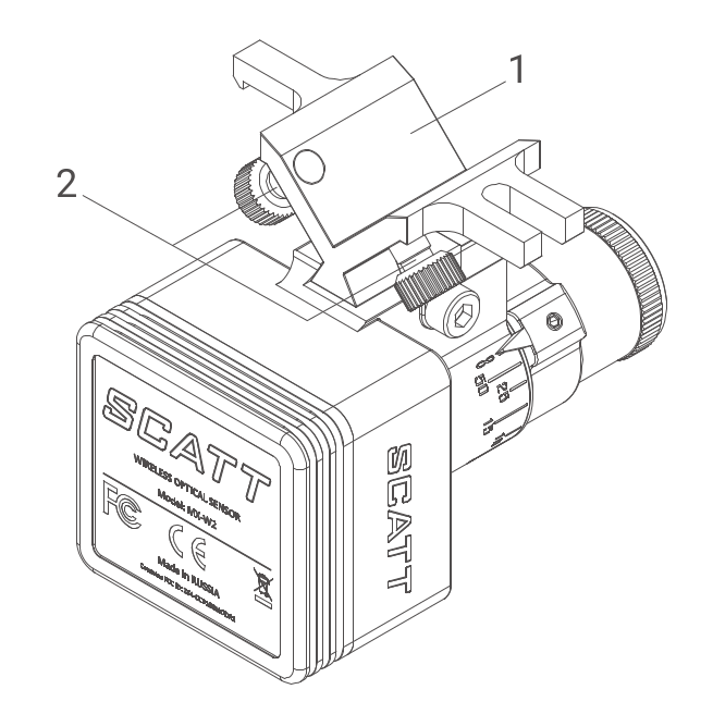
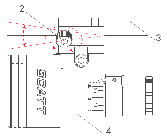
This sensor is equipped with an adjustable lens which will allow you to use it at different distances (2.5m and higher).
Before mounting the sensor on the gun, adjust the focus ring to the real distance between shooter’s position and the target (in meters).
Loosen the screw #11 and turn the focus ring, so that the pointer #12 coincides with the desired distance on the dial #10, then tighten the screw #11*
*Avoid applying excessive force to the screw #11 to avoid lens damage.
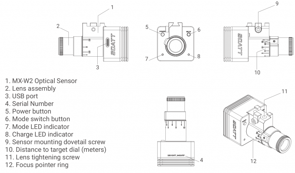
The optical sensor is powered by a rechargeable battery. It can be recharged via the USB port of your PC or a compatible USB charger.
The LED light on the sensor is orange during charging and switches to green when fully charged. A full battery recharge takes approximately 3 hours.
Depending on connection mode and use intensity, one charge lasts roughly 4 hours of continuous training.
Attention! In cases of long storage, you need to recharge the sensor at least once every 12 months, to
avoid permanent damage to the battery.
Mounting the optical sensor on the gun
Please refer to the following scheme.
Please refer to the following scheme.
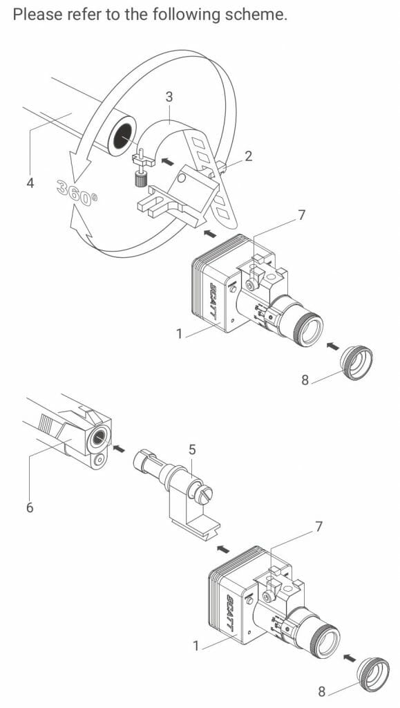
- Optical sensor
- Mounting prism
- Mounting strap with screw
- Barrel
- Barrel insert (not included in the set)
- Pistol
- Dovetail tightening screw
- Iris diaphragm*
Mounting options:
- Use the flexible metal strap and the v-shaped prism bloc, supplied with your system, to clamp the optical sensor to the barrel or any suiting part of the gun.
- The optical sensor can also be mounted with the optional barrel insert mount (barrel inserts are caliber specific)
The sensor can automatically compensate for cant, so you can mount it at any angle around the gun’s barrel.
Padding of any kind between the mount and the gun can dampen the vibration affecting shot registration, the mount must touch the gun metal to metal.
*The iris diaphragm is intended to limit the amount of light on bright and sunny days, do not use the iris indoors with artificial light.
Getting started (SCATT Expert)
Before the initial setup you need to install the SCATT software.
Insert the supplied SCATT flash drive into the USB port of your computer.
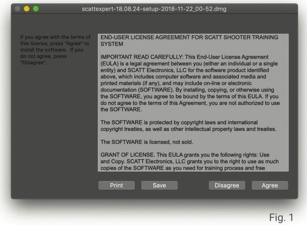
Run the scattexpert-x.x.x-setup-xxxx-x-x.exe file or scattexpert-x.x.x-setup-xxxx-x-x.dmg for macOS
and follow the on-screen instructions (Fig. 1). (There is also Linux SCATT software.)
All necessary software can be found on the supplied flash drive, but you can always download the
latest version of the software and manuals at: https://www.scatt.com
Connecting the trainer
There are three types of connection available on the SCATT MX-W2:
Direct Wi-Fi connection mode

LED light below the Power button is blue. The sensor creates an open Wi-Fi network with a name similar to: SCATT_XXXXXXXX (exact network name is written on the sensor).
Turn on the optical sensor by pressing the power button. The LED light below the power button should start blinking blue.
Blue blinking indicates that the sensor is in direct connection mode. Turn on Wi-Fi on your PC or mobile device and connect it to the SCATT_XXXXXXXX network.
When the system is connected the LED (7) will turn from blinking to solid blue.
Your PC or mobile device will not have an internet connection in direct connection mode. You can use it when you are away from your trusted Wi-Fi networks.
Network connection mode

Green LED light below the Power button.
The sensor can connect to your PC/tablet/ smartphone via the local Wi-Fi network.
Your network environment and Internet connection (if present) will be accessible.
To configure this mode, you will need to pair the SCATT sensor with the local Wi-Fi network.
You can use either the WPS fast pairing (read below) or enter Wi-Fi profile (ID and password) in sensor’s settings of the SCATT software under the About tab.
To connect the sensor to the local Wi-Fi network with the fast WPS authentication you need to set the sensor to network mode (green LED) with a single short press of the Mode button. Once the LED below the power button is blinking green press and hold the Mode button until the LED turns orange, release the Mode button and the LED will blink in series of two quick flashes.
After that press the WPS button on the body of your Wi-Fi router and the Wi-Fi profile of this network will be added to sensor’s memory and the sensor will connect to it automatically. The LED below the power button should turn solid green at this point.
The sensor supports 2.4 GHz networks with a 20MHz channel.
Direct USB connection mode

Yellow LED light below the Power button.
Simple USB connection from sensor to PC. This mode allows both training and access to all possible sensor settings.
Switch between connection modes by quickly pressing the “MODE” button on the sensor.
New practice
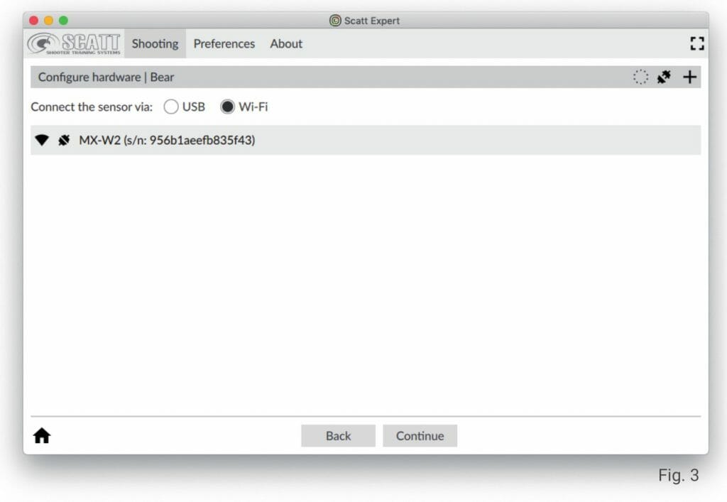
From the main page of the software interface click the “Start Practice” button. First time the system will prompt you to add a user name, click continue after that. Hardware configuration screen will open (Fig. 3).
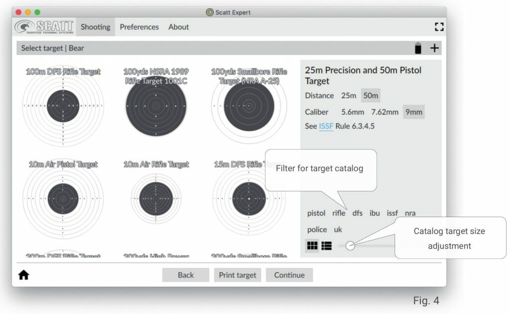
Choose the wired or wireless connection mode and select your device below, click Continue after that and the target catalog will open (Fig. 4).
Targets
Pick the desired target from the list on the left side, set the distance and caliber (if different options are available for the selected target) and press Continue. The system will go into calibration mode (Fig. 6).
For training at standard (real) distances you can use standard issue paper targets or electronic scoring targets.
For training at reduced distances, at home for example, you can print out a scaled down version of the target by using the “Print Target” menu (Fig. 5).
Printing a target
In this screen you need to input the real distance to the paper target measured from the sensor in meters, select other desired options and click “Print”.
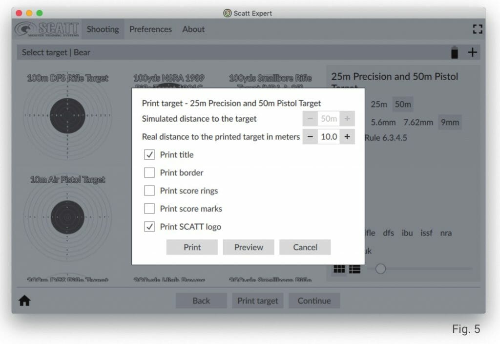
For indoor use the target must be evenly illuminated with intensity of no less than 1000 Lux (Light meter apps for smartphones can be used).
We recommend using “warm” LED lights (2700К) or regular incandescent or halogen lights.
Optical sensor calibration
In order to calibrate the optical sensor with your gun’s sights, carefully aim at the center of the paper target. The aimpoint (red dot) should appear in the sensor’s field of view (big black circle) on the screen. Take good aim and shoot.
The optical sensor will record the shot and register that coordinate as the center of the target. The program automatically combines the coordinate of your calibration shot with the target’s center.
You don’t need to make any adjustments to the sights of your gun.
For a more accurate calibration you can take several shots before proceeding to practice mode. In this case the average calibration coordinate will be counted as center.
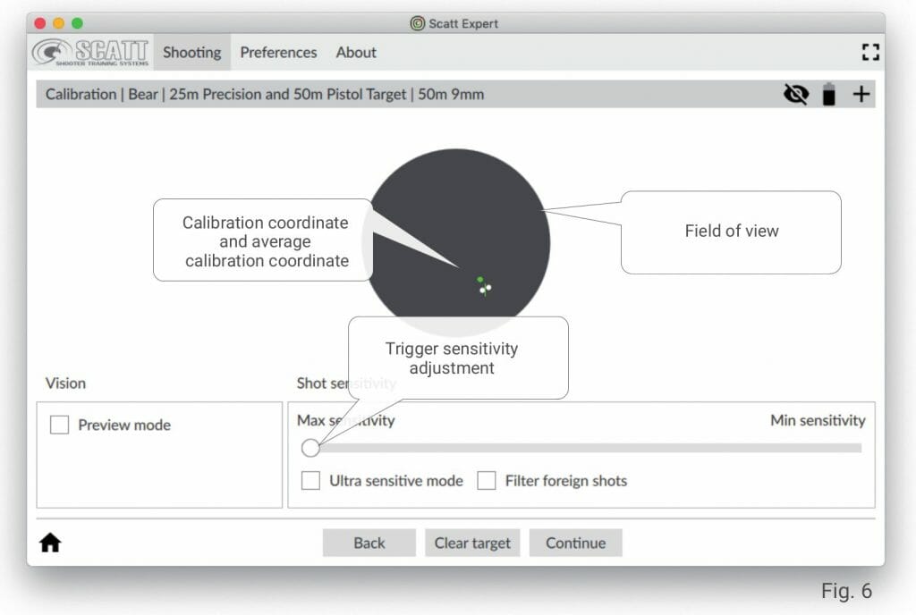
If you see the red calibration dot moving within the field of view, but it’s not registering the shot when you pull the trigger, drag the trigger sensitivity adjustment left and make sure that the sensor is tightly mounted on the gun without any padding between the sensor’s mount and the body of the gun (metal to metal).
If you don’t see the red aimpoint in the black circle while aiming at you paper target, switch to “Preview mode” (Fig.7), aim at the target again and make sure that your target appears in the field of view when you are aiming.
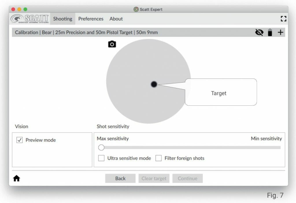
If it does not, use the brass adjustment screws in the v-shaped mounting prism to adjust the angle of the sensor until your view more or less coincides with sensor’s view, so that you can see the target image on the screen while aiming. It doesn’t have to be perfectly centered, but needs to fall well within the boundaries of the field of view.
- Mounting prism
- Adjustment screw*
- Gun’s barrel
- Optical sensor
Practice window
In this screen (Fig. 8) you will be able to see the trajectory of your aimpoint movement in real-time. The click of the trigger release will be recorded and combined with aimpoint movement speed and the ballistic coefficient in order to allow the software to display your shot on the screen.
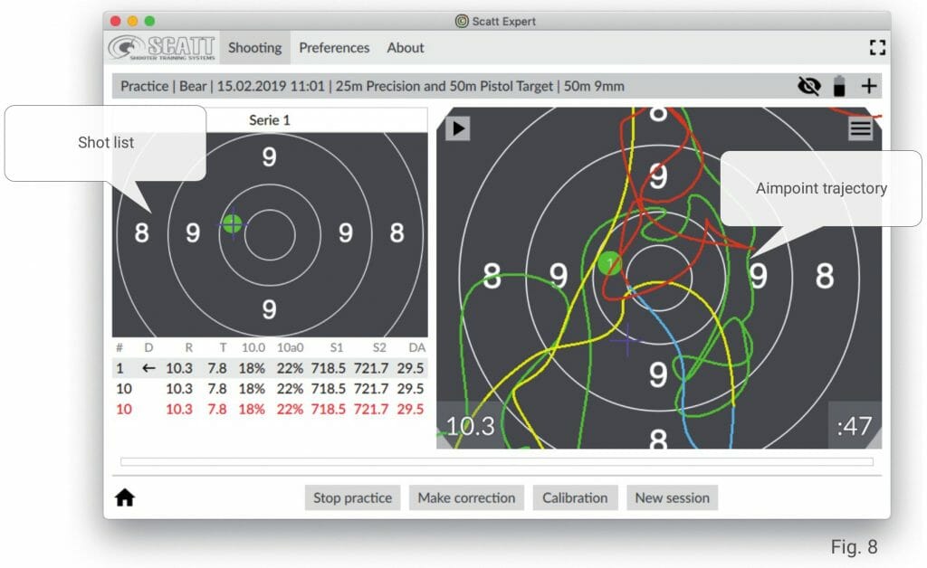
After each shot or at any other time, you can replay the movement of your aimpoint on the target and see the shot coordinate. The list of shots to the left of the target includes data about each shot: score, time of aiming, percentage of time within the 10-ring, average aimpoint speed, etc.) The aimpoint curve is color coded into different stages for ease of analysis:
- green – initial aiming stage
- yellow – one second before shot
- blue – 0.3 second before shot
- red – follow-through
All practice sessions are saved automatically and can be accessed later.
Scaling the target on the screen
You can always zoom in and out of the displayed target by pressing the number keys 1 thru 9 on your keyboard. This will scale the target to the respective scoring ring.
The target might automatically zoom out when the shot landed outside the currently displayed section of the screen.
You can also drag the target on the screen to view in detail any desired section of it with the left click of the mouse.
To return to default target size right click your mouse.
Making electronic corrections
If your average hold area or shot group are misaligned after calibration, you can make a fine-tune electronic adjustment.
In order to do that, select the last shot from the list of shots, click the “Make correction” button, and click on the target where you think the last should have been.
Press the “Make Correction” button again or just begin aiming for the new shot.
After that, all subsequent shots will be displayed with this adjustment in mind.
We recommend re-calibrating if your shots are grouped outside the 8-ring.
Other features
For a complete analysis of the shooting results the SCATT Expert program displays information about each shot in digital and graphic forms.
The analysis of the aimpoint trajectory enables better understanding of the result and identifying
errors in aiming and triggering.
The software displays several different types of graphs and data points that allow the shooter
to obtain comprehensive information about his/her performance.
You can set the data points to be displayed in the Shot List under the “Preferences / Shot list” tab.
The following data is available:
- No – Shot number
- D – The position of the shot relative to the center of the target
- R – the score
- T – aiming time
- 10.0 – the percentage of time your aimpoint was within the 10 ring in the last second before the shot (control time interval can be adjusted in settings)
- 10a0 – the percentage of time your aimpoint was within the “absolute” 10 ring (imaginary 10 ring around your average shot coordinate, displayed as a yellow cross on the target) in the last second before the shot (control time interval can be adjusted in settings)
- S1 – aimpoint speed in the last 1 second before the shot
- S2 – aimpoint speed in the last 0.25 seconds before the shot
- DA – is the distance between the center of the target and the center of the shot.
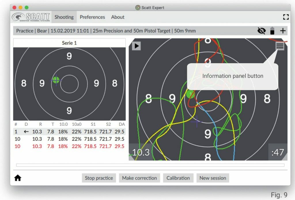
To view additional graphs and parameters, open the information panel by pressing the button with three parallel bars (Fig. 9).
The additional information panel (Fig. 10) contains the following: image of the target with all shots in the current practice session, ballistic F-coefficient setting, “Distance” graph, “Coordination” graph, “Time shift” graph, “Average trace speed” graph. At the bottom of the practice window you can find a white strip with red marks, this is the linear graph of the time intervals between shots.
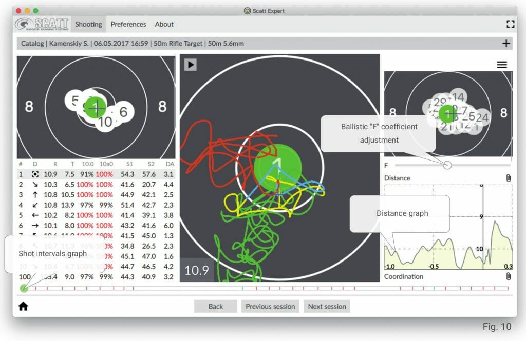
The ballistic “F” coefficient changes the value which affects the dispersion of shots on the target. The program changes the dispersion dynamically on the target when you slide the adjustment bar, depending on the value of the coefficient. The average “F” value is set as default for each exercise.
The linear graph that displays time intervals between shots is shown in the form of a dynamic time scale on which vertical marks represent the shot moment (10s are displayed in red, all other scores are blue). The highlighted shot is displayed with a round marker. Judging by the distance and evenness of the spread between the marks, you can visually see how uniform is your shooting.
On the “Distance” graph you can see the absolute distance from the center of the target relative to time for the highlighted shot. The graph gives can help you understand of the nature of your movements caused by non-coordinated muscles and tremors.
The “Coordination” graph refers to the shooter’s ability to choose the best moment for shot release depending on his stability.
The shooter’s ability to pick the right moment for shot release may partially compensate the lack of stability.
To measure coordination the system uses a graph of average values R(t)=square root of X²(t) + Y²(t), built within a certain interval preceding the shot.
The R(t) value and especially the nature of its changes (increase and decrease) in the last 0.2 – 0.3 second preceding the shot can be used as a measure of the shooter’s coordination. The stronger the increase in the value of R(t) in the last 0.2 second, the worse is the coordination, i.e. the more often the quality of hold deteriorates at the moment of trigger release.
The “Time shift” graph shows the correlation between the shot moment and the result of that shot. You can see the graph of potential scores if the shot would have been taken at any time earlier. The “Average trace speed” graph shows all the changes in the speed of your aimpoint at any time during your aiming process.
Each graph has a small paperclip button that you can use to clip that graph to the bottom of the target screen. (Fig. 11). In this case the selected graph will show in a semi-transparent form even if you close the additional info panel. It will automatically hide during each aiming and shot replay.
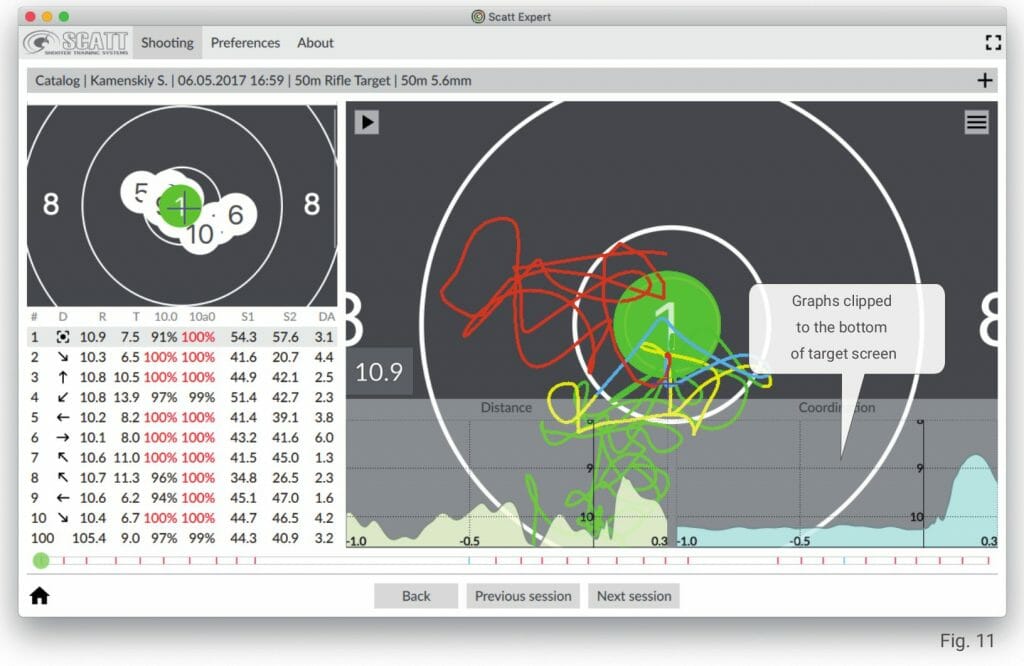
Go back to the additional info panel and press the respective paperclip again to hide the graph from the target screen.
Saved practice review
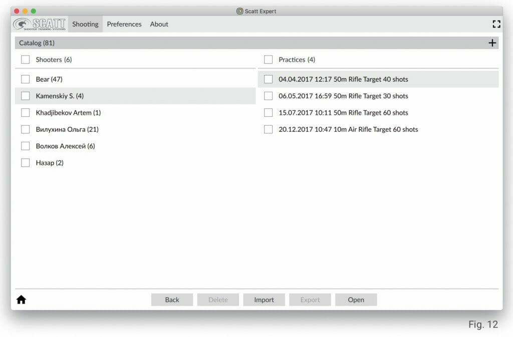
The SCATT Expert software automatically saves all your practice sessions and groups them by shooter’s name and date.
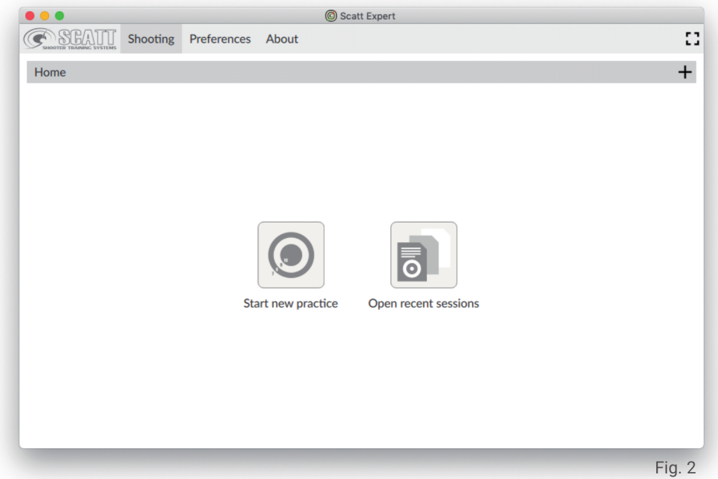
Launch the SCATT Expert software and click “Open recent sessions” to access your previous training sessions (Fig. 2).
Then select the shooter and the practice that you would like to review and click “Open” (Fig. 12).
You can review your training sessions on other computers and pass them on for review to other people.
In the same menu select a practice file and click “Export”, then enter a name for the file and select the desired file location.
To open the file on another device you will need to install the SCATT Expert software on that device.
To open the practice file go to “Open recent sessions”, click “Import” and select the file location.
Program settings
Use the “Preferences” tab to access SCATT Expert program settings (Fig. 14).
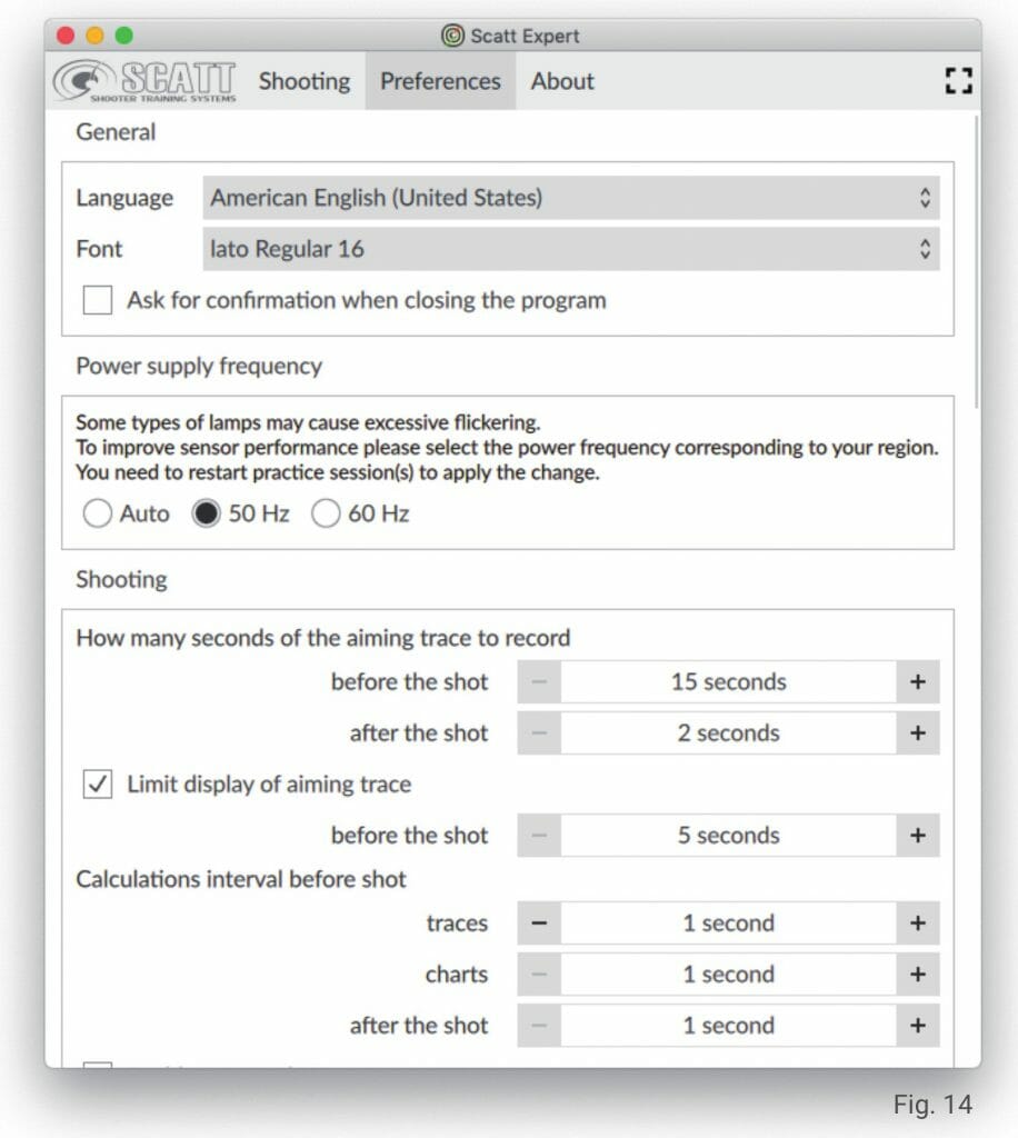
You can change the language, font style and size (adjusting font size will also alter the size of other objects in the menu), colors, etc.
You can always restore all setting to original condition by pressing the «Default» button.
To delete all your saved practice files use the «Reset storage» button.
About system | Diagnostics
Use the “About” tab to access information about the current version of your software, directly access the SCATT website to check updates, and to open the “Diagnostics” panel of the connected system (Fig. 15).
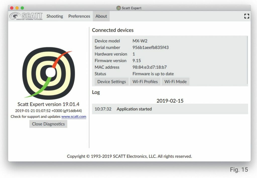
The “Diagnostics” panel contains the following information about the connected sensor: model, serial number, firmware version, and the update status of your current firmware.
The “Device settings” option will allow you to set a password for your sensor’s Wi-Fi network (for direct wireless connection, change the active channel and the sensor’s ip address.
Under the “Wi-Fi Profiles” option you can also add credentials for new Wi-Fi network profiles to be added to your sensor’s memory.
The system can remember up to seven profiles of known Wi-Fi networks to which it will be connecting automatically if all the credentials were added correctly to respective profiles.
Click the “Add” button, enter the network’s name, password (if applicable) and click “OK”.
The network profile credentials will be saved in the sensor’s memory.
To delete a profile, select it from the list and click the “Delete” button.
The “Wi-Fi Mode” will allow you to switch the sensor between the direct wireless connection (blue) mode and the network connection (green) mode.
Attention! When the connection mode is switched, the optical sensor will reboot and communication with it will be temporarily lost. To restore connection, you must make sure that the sensor and the computer are connected to the same Wi-Fi network or that the computer is connected to the Wi-Fi network of the optical sensor (in direct connection mode).
Restore optical sensor’s settings to default
To reset all sensor settings, turn on the sensor with the “POWER” button, then press and hold “MODE” button for about 20 seconds until the operation mode indicator lights up red, then release the button.
The sensor will reboot and all settings will be returned to factory settings.
Care
Use dry soft cloth to clean the body of the sensor. To remove heavy dirt you can use a cloth with light solution of soap or detergent.
Use special optic wipes to clean the sensor’s lens.
Never use paint thinners or gasoline to clean the sensor or the accessories.
Specifications
Sensor size: 34 х 35 х 60 mm
Sensor weight: 56 g.
Available connection type: USB / Wi-Fi (2.4 GHz, bandwidth 20 MHz)
Operating temperature range: from -20 to +450 С
*The manufacturer assumes the right to implement changes that will not lead to a deterioration in the quality of the system’s functionality at own discretion and without additional notifications within or outside this manual.
Contact
SCATT Electronics LLC
141551 Russia, Moscow Region,
Solnechnogorsky rayon, pos.
Andreevka 3-B, office 56
Tel.: +7 (499) 504-93-74
E-mail: [email protected]
www.scatt.com